Visual Studio Express 2005
Visual Studio Express 2005 SP1 Update
XNA Game Studio 2
XNA Content Compiler [ MIRROR ]
XNB Model Viewer 2 (optional)
3D Studio Max 2008
Photoshop
ZBrush 3.1 (optional)
Tutorial max file with dummy note (max 2008 only)
Install visual studio
Install the SP1 update
Then install XNA Game Studio 2.0
Make a new folder for your project and extract the content compiler into this folder
Now everything is setup we can get on with the modeling so go ahead and open up max.
[ BACK TO TOP ]
First thing to decide is are you going to be working to reference or not. If you need to make something accurately then you will want to work
over reference, its up to you.
For this tutorial I will be making Mario mushroom notes. So to start google is your friend, find some good reference images so you know
exactly what u want it to look like, if your making something original then you would draw some concept designs and maybe some front and
side views that u can use to build from.

NOTE - If you want to make something without reference you can skip this section, all good work is made from reference but
for learning / experimentation this is not required.
To get your reference image setup you will want to draw a plane, do this in the front view.
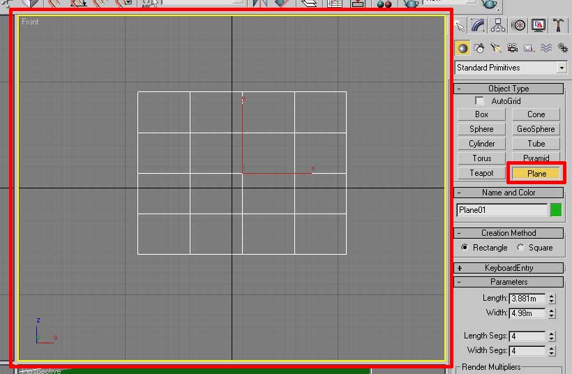
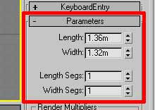
Set the width and height to match the aspect ratio of your reference image, ie my mushroom image is 132 (width) x 136 (height) so i could set the
length and width to 1.32m and 1.36m or you could do 132m x 136m if you want, either is fine as you only need the aspect ratio
correct, the scale is not important.
Note - Make sure you get the length and width the right way round as the first value you enter in max
is the height not the width.
Also set the length segs and width segs to 1
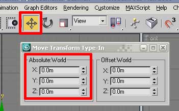
Move the plane to 0,0,0 world coordinates, with the plane selected right click the move tool button and set all 3 absolute world values to 0
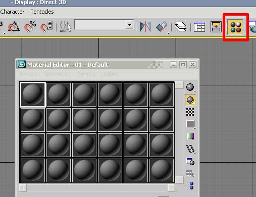
Now we need to setup the material to put on the plane, open the material editor by pressing M or clicking the material editor
button in the top menu.
click on the diffuse map button
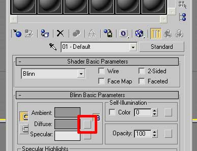
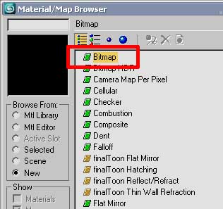
Select the type as bitmap and select your image
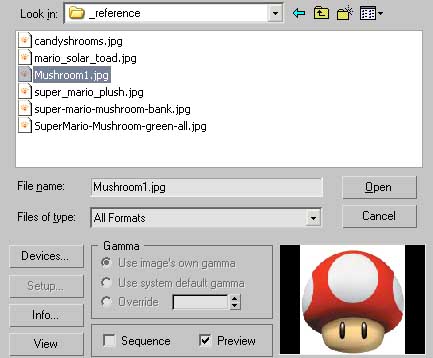
Now find the image on your hd and open it up.
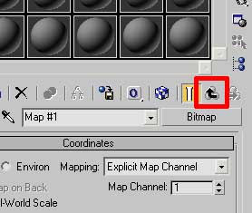
Click the up arrow to get back to the root of the material
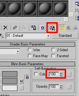
Click the blue box to enable material display in viewport and slide the self-illumination to 100
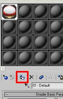
Now we can apply the material, if you don't have the plane still selected, select it and click the apply material to selection button
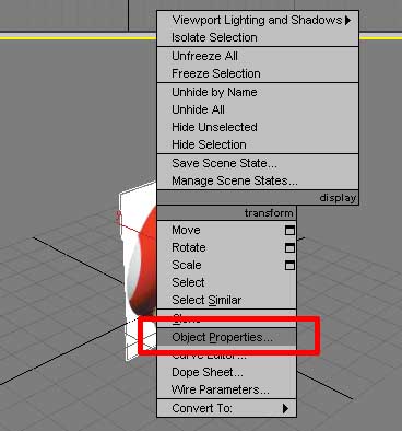
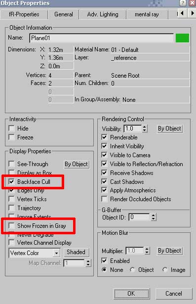
You can now close the material editor, next right click on the plane go to object properties and untick the option show frozen in grey and tick backface cull then close the window.
Make sure the plane is still selected, and open the layers window and make a new layer called _reference, the selected objects will automatically be
moved to the layer.
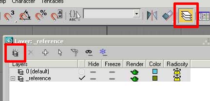
Then tick the freeze button on the reference layer and tick the square next to the 0 default layer, the freeze option locks the objects in that layer
they remain visible but can't be selected. The tick next to the layer name makes this the active layer so any new objects will be made in this layer,
we don't want the reference layer ticked as anything we make would be frozen.
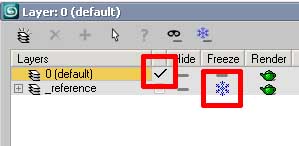
Now we have our reference image setup we can start modeling, now would be a good time to save the file, i'll be saving mine mushroom_01.max and putting it
in the folder along with the content compiler application.
[ BACK TO TOP ]
When modeling for games you always want to keep in mind your poly / triangle counts, max has a nice option to display
some of these details in the viewport, but the default setup is not very usefull so we need to adjust some settings.
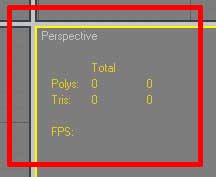
Right click on the Perspective view title (top left) and select configure.
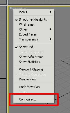
Then go to the statistics tab and enable triangle count, disable vertex count and change the mode to Total + Selection and tick
show statistics in active view and click ok.
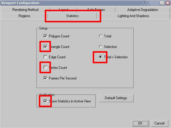
Now you should have the details you need showing up in yellow inside your viewport. The left numbers show the entire scene details
while the right values show the details of the objects you have selected, very usefull.
[ BACK TO TOP ]
Some usefull keyboard shortcuts that will be made use of while modeling.
Grid
Face Selection Fill Toggle
Wireframe / Textured Display
Edge Display
Xray Mode
Sub object selection mode
Move tool
Rotate tool
Scale tool (3 modes)
Material editor
Statistics display
Maximise viewport
Front view
Top view
Left view
Perpective view
View select menu
Selection box display
Undo
Redo
Viewport Undo
|
G
F2
F3
F4
Alt + X
1 to 5
W
E
R
M
7
Alt + W
F
T
L
P
V
J
Ctrl + Z
Ctry + Y
Shift + Z
|
[ BACK TO TOP ]
I won't go into to much detail with the modeling process if you need more in depth details you will need to look up
a general max modeling tutorial, theres plenty of them about.
But there are a few points to cover that may not be found in general tutorials
Only have as many polygons as needed to get the shape u need to make, if you have divisions along a flat area then
its wasted polygons. Also consider the distance the model with be viewed from, when judging how many polygons a rounded
area will need to look smooth, view it from the actual distance the model will be viewed in game. Generally while modeling
you will be looking at the model close up so you may be tempted to add a lot more polys than are actually needed, zoom out and
then decide what is needed.
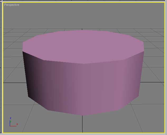
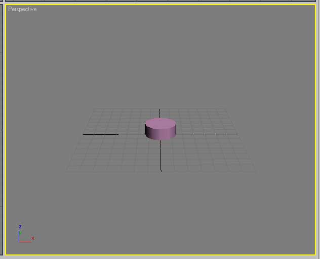
To demonstrate this i will make a cylinder with 12 sides, when viewed normally the edges seem very chunky, but then when we view
it at a similar distance to how they will be viewed inside the game it looks quite round, so keep in mind the more polys you use
for the note models, the less are avaliable to use for the backgrounds so keep things optimised.
I find the grid in perspective view can get a bit distracting so can toggle that with "g" I will also select the front viewport (middle mouse button)
and press F3 to go to textured display so we can actually see the reference image.
There are many methods that can be used to model, we need to consider the shape we need to make, for this example I have gone with the mushroom
Try to break the shapes down into their basic shapes, for this the base could be a cylinder or a square and the top part is similar, but could also
be a sphere. For this model I will start with boxes and add the detailing.
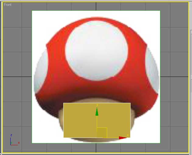
I will create new objects in the top view to ensure the pivot points are aligned correctly. So here i drag out a box roughly the size i need and
move it into the position i want it to be. I find the selection edges can be annoying so I press "j" to hide those, and I also want the polygon
edges to show up so pressing F4 will show those. So we have something that looks like this.
One of the nice tools in max is the xray mode (Alt + X) we can use this to see through the model, this can easily be toggled on and off while working to
see how the shape aligns to the reference image.
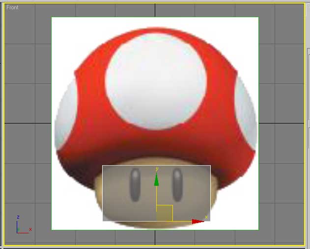
Now Im going to right click on the model and convert it to an editable poly and then start refining the shape.
NOTE - Save often, use the + button in the save as dialogue box to automatically increment the filename without needing to type.
NOTE2 - When modeling you should be keeping all the polygons 4 sided (quads) avoid triangles and ngons (5+ sided polys) as this stops the
model being able able to sub divide properly and can lead to glitches.
Here we have the basic shape coming together.
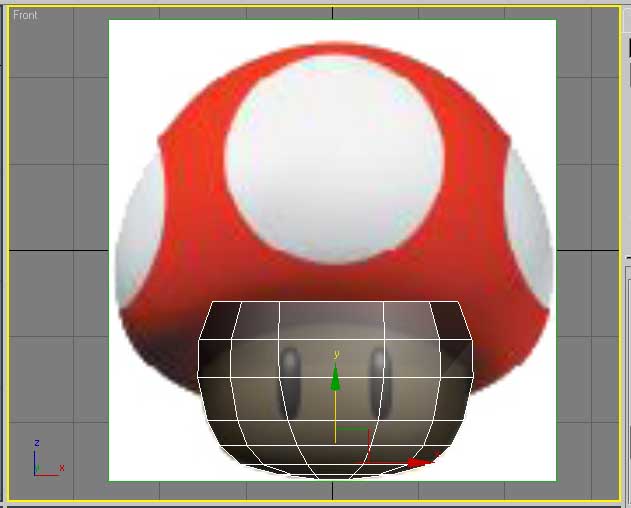
For the top part of the model I will use the bottom part as a base shape, and use symmetry to make the top and bottom the same so I have a simple
low poly round shape that is a little nicer to work with than just creating a sphere. I avoid using the sphere because this has triangles around the
peaks. Shaping a box will maintain a quad layout.
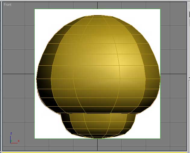
After a little more refining the shape we have something that seems to represent the thing we are trying to make. At the moment there are a few more
polys than I really need but I haven't gone so far that it will be a problem to remove a few loops to keep things optimised. Later on I will make a duplicate
of the model, remove a few polys and view them both at a distance to see if theres any noticeable problems. I prefure to work a tiny bit higher than I need
to at first just to get the shape right, and then work down.
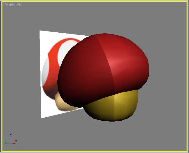
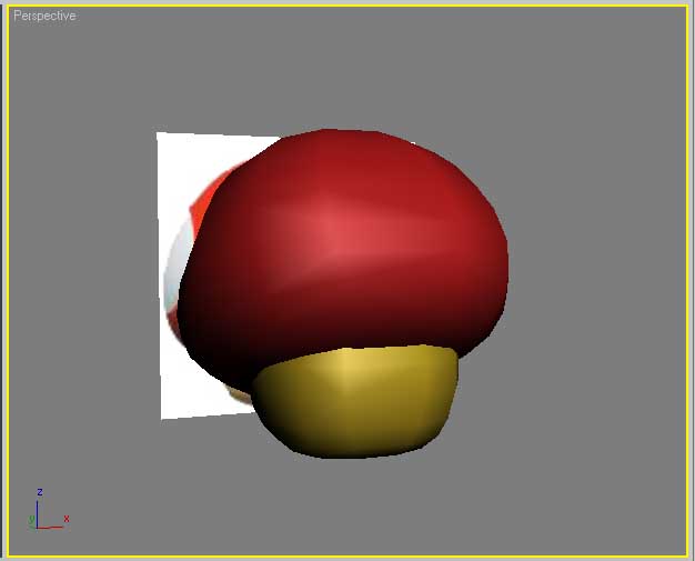
In the image you can see there are some weird shading issues going on, this is due to the original shape being a box and even though the shape
has been rounded off, the smoothing groups are telling it there is a corner there, that is where the original corner of the box used to be.
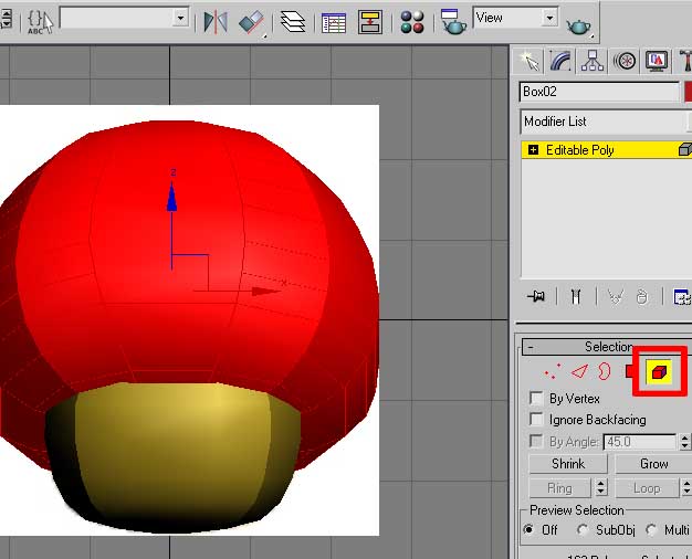
We can fix this by adjusting the smoothing group settings, select the object, go to the element sub object mode "5" and click on the object so
all the polygons on the object are selected.
Note - Press F5 to change how selected polygons are displayed if you want.
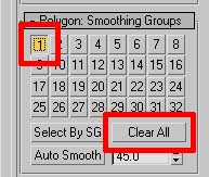
Now go to the Polygon Smoothing Groups section, clicking clear all will remove all smoothing, this can be good if u want to go for a low poly look.
If you want all the polys to be smooth after clearing you can click 1, this will set all the polys to the same group. If you want some edges / corners
then you can switch to sub object mode 4 (polygon) and select the polys and apply groups where you need. Or an alternative method is to set a threshhold
value and click the auto smooth button. But for my model there are no hard edges so I want all the polys to smooth.
I do this for both objects and we have a much nicer result.
[ BACK TO TOP ]
As I mentioned before my model is currently a little higher detailed that it likely needs to be, so we will test how much detail we can
remove without loosing the shape we want. Currently the model is 254 polys / 506 triangles.
Now im going to duplicate the model, move it to the side and remove a few edge loops. Only after a few changes I have knocked the duplicate
down to 162 polys / 324 Tris. Even close up with haven't lost a lot of detail, but when viewed at a distance the difference its very small.
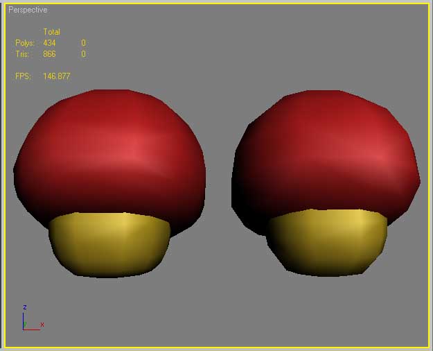
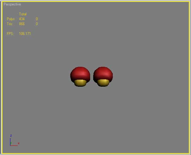
There are other methods to optimise further but nothing more needs to be done at this stage of development.
[ BACK TO TOP ]
Before we can make the texture for the model we need to setup the uv coordinates, a process of flattening the 3d mesh into 2d space,
there are a number of approaches to this, and you need to strike a ballance between a layout that represents the shape well enough to
be able to make the texture properly, while keeping texture distortion to a minimum and seams hidden as well as possible.
for a note that can only be seen from the front view it means we can put the seams along the back of the model as this would be hidden
from view, but for this model we should be able to unwrap it without any seams quite effectively, as the model is basically 2 domes
so if we go from a top / bottom view these can be flattened easily.
I'll start off by doing the top part, select the model and add a uvw unwrap modifier to it, then expand the unwrap modifier and select
Face mode.
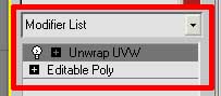
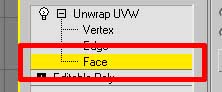
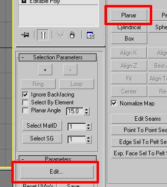
Now for this shape I will project the mapping from the top view and then pull the sides out, so I select the planar map option and then
either align to the z axis or use the best align option. The best align option works quite nicely for this situation so I will go with that.
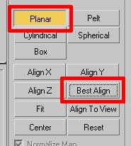
Once the map is aligned as desired you have to disable the map mode, click the yellow planar button to disable it and then click the Edit... button
in the parameters section and a new window will come up, this is where we can view and edit the mapping.
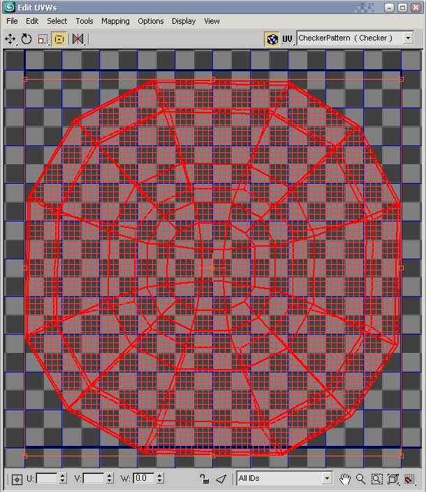
NOTE - If you haven't disabled the mapping mode the edit uvw window will be locked, so if you are unable to do anything this is usually
the reason why.
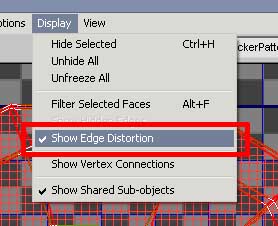
If you go to the display menu there is an option "show edge distortion" this shows all the problem areas with the current mapping, green is good
red is bad, we need to adjust the shape to get as much green as possible.
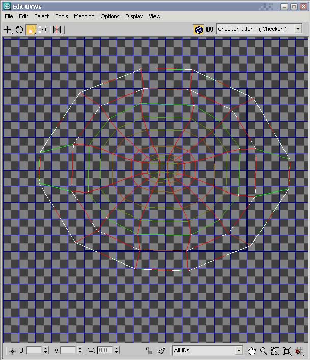
The next thing to do is make some adjustments to get things in the rough shape we need, at the moment we have overlapping faces where the top
and bottom are occupying the same 2d space, so i will do some manual adjustments to fix this, i'll switch to edge mode in the unwrap modifer and
select a loop that is overlapping, then in the edit uvw box i'll scale this up, and repeat untill all the overlapping has been removed.
The result will look something like this.
The next thing to check is if the unwrap is inverted, do this by going to the select menu and clicking the select inverted faces option if everything
goes red use the mirror horizontal button to fix this, if it doesn't go red then everything is fine.
NOTE - If the uvw's are inverted the next step may go wrong so be sure to do this first
While the overlapping has been fixed there is still a lot of distortion going on, luckily there are a few tools to help this, go to the tools menu and
select the relax option.
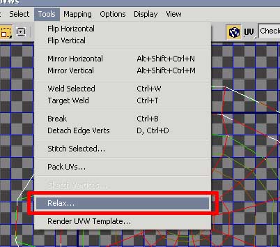
Flick back to face mode and select everything (can tick the Select element option at the bottom to select everything easier).
In the relax tool dialogue box there are a few options, i generally get good results in the Relax by face angle mode so select this
and click apply a few times and see how it effects the shape.
As we have gone for a no seams method of unwrapping it is going to be impossible to get perfect results but it should be fine for this.
You can now close the edit uvw window and to finish off collapse the modifier stack to bake the uvw coordinates into the model.
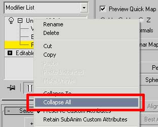
Now this process needs to be repeated for the other part of the model. Once this is done we should check for distortion by applying a test
material to the model that will easily show up any problems. The easy way to do this is to make a checker material.
Press "m" to open the material editor, select a new material slot and click the diffuse map button, just like we did before with the background
reference image, but this time instead of selecting the bitmap option select checker.
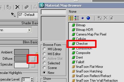
Now click the up arrow to go back to the root level of the material and click the blue cube button to make material visible in the viewport,
select your model and click the apply material to selection button.
Now it is likely the texture will need to be tiled to show enough detail, so click on the diffuse map box again, this time there will be a M written
on the button, this is because there is a map now assigned to it, while before it was empty. Now inside the checker map settings there will be a
U and V tiling value, by default it will be on 1 but we want to increase this. Depending on the size of your model you may need to experiment with a
few different settings, try 10, and adjust up and down as needed.
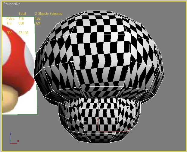
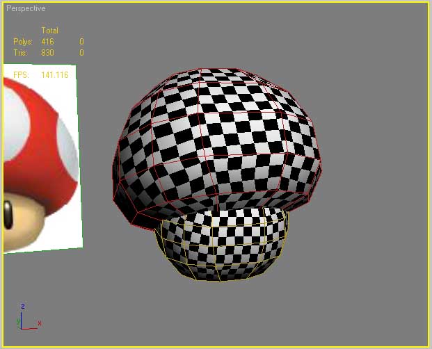
From this image we can see how the texture is going to distort when applied to the model, in a perfect world the each square of the checker patter
would be even with minimal stretching as it goes around the model, but as we can see from the image there are some major issues with the current
unwrap, so we can try and adjust the current mapping to try and fix this, if we can not reduce the distortion to a reasonable level we will have to
resort to adding seams to the model.
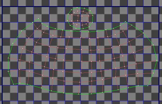
After spending some time tweaking the unwrap I decided it would be best to go with the cylinder unwrap and have a seam along the back and the top,
seams can be tricky when dealing with a sphere as there are no natural edges that seams can hide in but for simple shading seams are easily painted
out, so I can get away with having seams in the flat coloured areas quite easily.
When all the model is unwrapped it needs to be layed out suitablily, Select all the parts together and apply a uvw unwrap modifer again,
but this time it will apply to both parts at the same time
NOTE - This feature only works in max 2008 or newer, in max 9 you will have to do the layout 1 object at a time, or
you can attach all the objects together into a single object to do this.
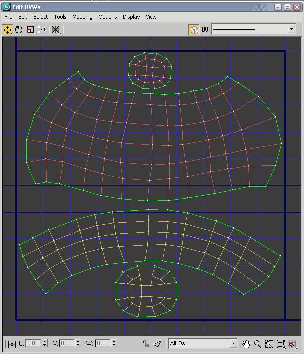
Click edit and you well see the both objects together in the edit uvw window, now tick select element and scale the objects to fit everything inside
the blue square, this is the boundry that everything needs to be inside. While scaling objects try to keep things in relative proportion to eachother,
and also try to keep sections as large as possible, so don't waste any space. This is the kind of result you will be after.
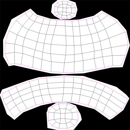
Now things are placed as we want them we need to save out a template file that we can use to make the texture properly.
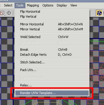
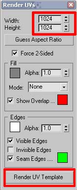
Go to the Tools menu and select the bottom option Render uvw template and a box will pop up, here we can set the size of the image.
You may want to set this to the same size that you plan to make your texture at, 1024 should be plenty as the notes are so small the
final texture could easily be 256x256 but personally I like to make higher resolution textures and then scale them down later for the
final export.
Click the render uv template button and a new window will come up with your template, now click the yellow floppy disk button in the
top left to save this as a bmp or png (or any other lossless format). This will be our base image to create the texture from. Once the file
is saved you can close all the floating windows and get back to the main max window.
Once all this is done you just have to collapse the modifier stack once again for both objects and the new layout is baked into the meshes and
we are finished with this stage.
[ BACK TO TOP ]
Texturing has a couple of routes, you can go straight to photoshop and start painting, or there is a projection technique that can be
done with zbrush, the zbrush method is great if you have a model thats very accurate to the reference and the reference is a high quality
image with lots of details that might be lost if you started to mess around with it in photoshop.
The mushroom used for this tutorial is cartoony and low detail so photoshop will handle the task quite nicely, I may talk about the zbrush
method later.
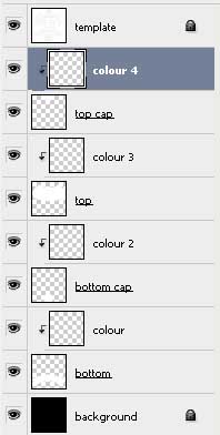
The way i like to set things up in photoshop is to bring the template into photoshop, by default it comes in as a locked background layer,
double clicking on the layer name and clicking ok will unlock it, now make a background layer to go under it and fill it black.
Then invert the template (ctrl + i) and set its blend mode to multiply
now to keep things clean i like to block out an area for each object and fill it white, this acts as a mask so i can work on one object
at a time without worring about overlapping lines, often templates get really crammed in and its easy to draw over areas you don't want
so this is just a way to make sure u only touch the object you want without having to erase all the time.
The setup should look something like this.
To start with we will just make a very quick texture to see how it looks on the model, so all I have done to start with
is get the base colours roughly right and paint a few white spots and black eyes, this is purely a 2 min task for testing.
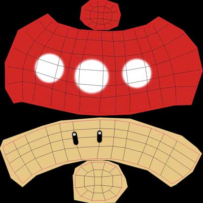
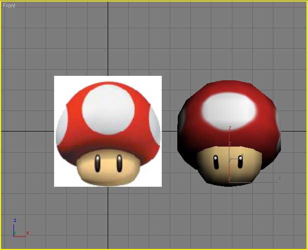
Here we can see the basic idea is starting to come together, make a few adjustments to the eyes and spots and we'd have a reasonable low poly remake.
Now there is something to consider, while making the texture you can paint the shading into the texture or you can let the games lighting deal with the
shadows and lighlights. Painting it in gives u more control over the look, but means all the shading is static while letting the game do it means highlights
can move depending on the notes position. Depending on what you are making different methods will give better results but personally I tend to paint the
shading in myself for this game as the lighting setup generally doesn't give the results I want.
So for this we take advantage of self illumination, this is a setting in the material, we can either go full on, 100% self illumination, this means all the
games lighting will be completely ignored, or you can go for a happy medium maybe 50-80% may give u the control you need while taking advantage of some
of the games lighting. This is purely an experimental process, try it one way and see how it looks, if your not happy try another system.
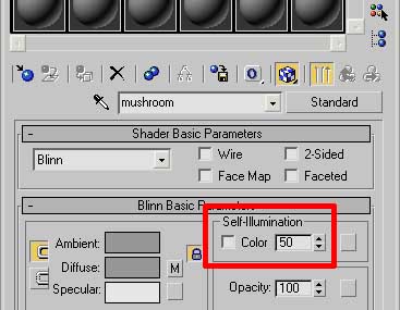
For this tutorial I am just going to set it to 50% self illumination for the moment and see how that works out for us. But I may end up going up to
100% later.
Now I will spend some time updating the texture as needed untill I am happy with the result. After a bit of tweaking things start to look a little better.
After some tweaking I decided to add a few more polys to the mesh to help the texture work a bit smoother over the edges. I also bumped the self illumination
to to 80%.
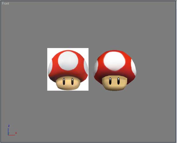
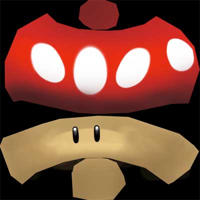
So now we have a model and texture in place we can do some colour variations. To do this I usually setup some hue saturation adjustment
layers in photoshop, one for each colour. This enables me to make changes to the master texture and then just turn on an adjustment layer
to save out the different colours. Much better than having to adjust 12 seperate textures every time I want to update the texture.
Once I have all the colours saved out I go back into max and in the material editor bring in all the different materials. By default max may only
show 6 material slots, but you can right click on one of the material spheres and select the 6 x 4 option to see more at once.
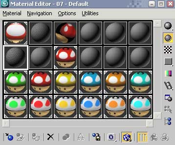
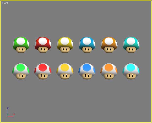
Here I have duplicated the model and applied the materials to everything just for demonstration you can do this but its only to see how they look and
not something that needs to be done.
Next we need to get the model ready for exporting.
[ BACK TO TOP ]
Exporting has a couple of complications but once you get the hang of it, it can be quite a simple process,
firstly the model needs to be positioned and aligned correctly, to make this step easier I have included a
max file you can use to make sure the model is in the right place. You don't need to use it, but it might help,
link is at the top with the other software links incase you missed it.
Merge my file (requires max 2008) into your scene, file menu > merge. The basic idea is to move the model
to 0,0 so it is sitting on the grid as it if is the ground, then rotate the model back 90 degrees, since
the up axis is different in max as it is to most games.
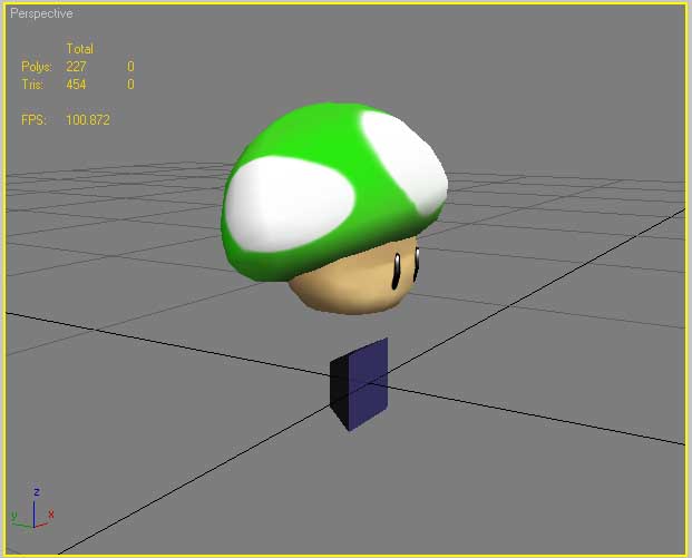
NOTE - The FBX exporter has an option to change axis so this may allow the model to be
exported normally but I do this manually since it was not working when I first tried and I never bothered
to check it again since to work out why.
Now your model should be scaled properly and in the right position, so the dummy note can be deleted.
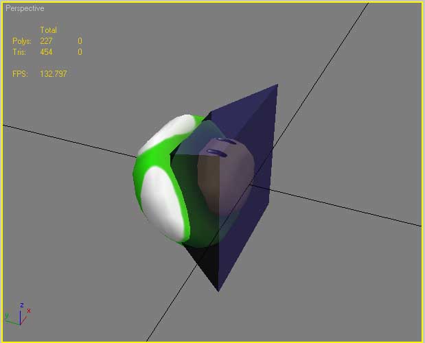
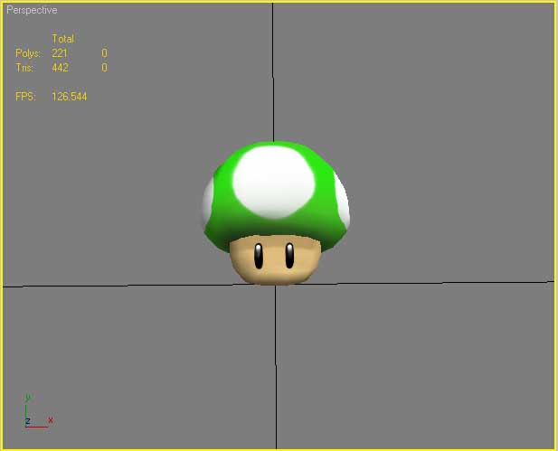
I have found that having notes with multiple objects can effect the orientation of the model, maybe because
the objects could be aligned differently and the game has to work out what orientation to use so if you want
to keep it simple to avoid potential issues just attach everything into a single object.
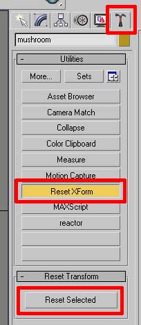
The next issue is that scale adjustments are ignored so we can use the reset xform tool to get the current
scale to be zero'd out.
To do this go to the utilities tab and there is a button Reset XForm, click this and another button appears below
saying reset selected, make sure your note is selected and click this. The reset xform is actually applied to the
mesh as a modifier so after this has been applied we want to collapse the stack once again.
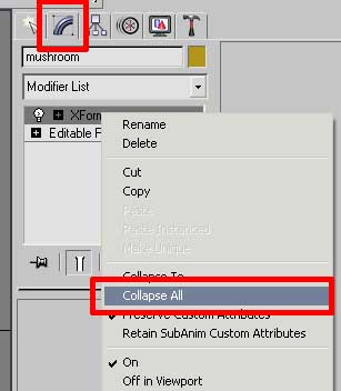
It is worth mentioning there is a bug in max that shows up when you reset the xform and export the model, sometimes the notes texture will
warp, this is nothing to worry about, its purely a max viewport glitch and the model is still fine. This can be ignored since it will probably
happen again if you keep exporting. But if you really want it to display normally straight away it can be fixed by going to sub object level 4
(polygon mode) and select all the faces and click the flip button, then come out of sub object mode and apply a normal modifier to the object
and then collapse the stack.
Now you may think this must be it, but there is one more issue to deal with. Guitar Zero 2 squashes models, so to get them
to display properly, you will have to scale the model to make it taller than you want it to be, ie if you have a square note,
it will show up as a rectangle in the game, if you have a circle it will end up oval, so we need to compensate for this.
I do not know the exact amount the game squashes things by so this ends up a trial and error process for me untill I am happy with
the result. For now we will just export the model as it is and then adjust it after.
NOTE - Every time we need to adjust the scale to compensate for the squashing, the xform process needs to be repeated
otherwise the changes will not show up in game.
So for now we just need to export out a test version to see how it looks, for this I just export 1 colour and rename it so it shows up as
all the notes in the game as theres no point exporting everything untill we have solved the squash problem.
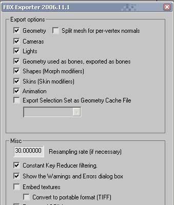
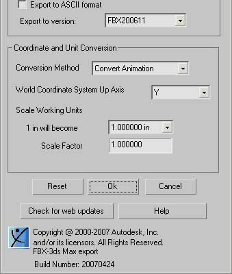
Go to the export menu and set the filetype to Autodesk (*.FBX *.DAE), and save the file as Note1_Normal, click save and the fbx export settings
dialogue box will popup. The default settings should be fine although technically you can untick options like cameras, lights, bones, shapes,
skins, animation since we are only exporting a static mesh. But you can just leave it as is and click ok.
Now you should have your fbx file and textures together in a folder with the xna content compiler exe. This bits nice and simple, open the
content compiler and drag your fbx file into it.
NOTE - Most of the time the content compiler seems to screw up or just work extra slow if I put more than 3 files into it
at a time, if you have trouble with it you may need to limit how many files you give it at a time.
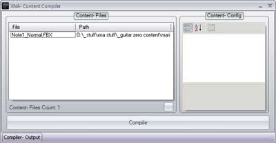
If everything worked properly you should end up with 2 xnb files, one for the note and one for the texture, these are almost ready to be used
in guitar zero. But before you try anything the texture file needs to be renamed so it ends with %0 this is an xna thing, and seems to apply to
all textures, so in this example, my mushroom texture is called mushroom_diffuse_green.xnb and I need to change this to mushroom_diffuse_green%0.xnb
Now assuming the fbx file was named correctly the xnb for the model itself should already be named correctly, if not then make sure this is named
Note1_Normal.xnb and copy two xnb files over into your guitar zero "resources\meshes" folder.
Now the files are in the right place we can load up the game and if everything has gone well the green note will now be your new model. Take note of
how it looks and decide if / how much the hight of the model needs to be adjusted.
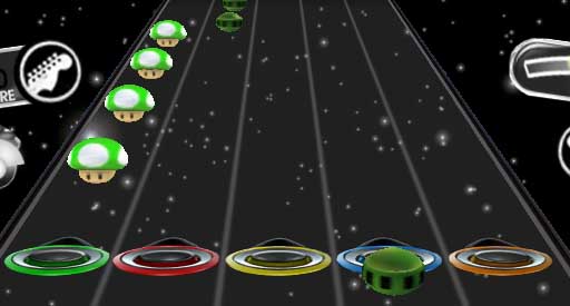
From this I can make a judgement on what I need to change so I will go back into max adjust it, export again and see how it looks, and repeat untill
its how I want. Then when I am happy with the single note in game I can export the complete set. For this model accurate height isn't that important
so I can just leave it as it is.
Once again bring all the fbx files into the content compiler, add %0 to the end of all the texture names and copy over to the game folder and you are done.
FILE NAME REFERENCE
NoteX_Normal
NoteX_HOPO
NoteX_Normal_SP
NoteX_HOPO_SP
|
Standard notes number 1 - 6
HOPO notes number 1 - 6
Standard Star notes number 1 - 5
HOPO Star notes number 1 - 5
|
NOTE - Only 5 Star Power notes since the 6th notes are for when star power
is activated and you don't have star notes when star power is active.
[ BACK TO TOP ]
That should be everything, here are screenshots of the final notes working in game.

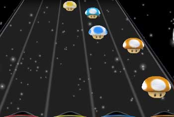
A complete gallery of my GZ notes can be found [ here ]
[ BACK TO TOP ]
|
|